- 您现在的位置:买卖IC网 > Sheet目录39245 > LM12H458MWG-MCP (NATIONAL SEMICONDUCTOR CORP) SPECIALTY ANALOG CIRCUIT, CDFP44
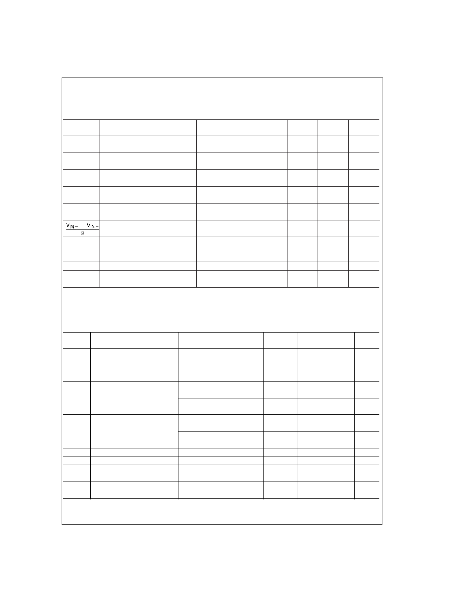
Converter Characteristics (Notes 6, 7, 8, 9, 19) (Continued)
The following specifications apply to the LM12454, LM12458, and LM12H458 for V
A+ = VD+ = 5V, VREF+ = 5V, VREF = 0V,
12-bit + sign conversion mode, f
CLK = 8.0 MHz (LM12H458) or fCLK = 5.0 MHz (LM12454/8), RS = 25, source impedance for
V
REF+ and VREF ≤ 25, fully-differential input with fixed 2.5V common-mode voltage, and minimum acquisition time unless
otherwise specified. Boldface limits apply for T
A = TJ = TMIN to TMAX; all other limits TA = TJ = 25C.
Symbol
Parameter
Conditions
Typical
Limits
Unit
(Note 10)
(Note 11)
(Limit)
8-Bit + Sign and “Watchdog” Mode
±1/8
LSB
DC Common Mode Error
Multiplexer Channel-to-Channel
±0.05
LSB
Matching
V
IN+
Non-Inverting Input Range
GND
V (min)
V
A+
V (max)
V
IN
Inverting Input Range
GND
V (min)
V
A+
V (max)
V
IN+ VIN
Differential Input Voltage Range
V
A
+
V (min)
V
A+
V (max)
Common Mode Input Voltage Range
GND
V (min)
V
A+
V (max)
PSS
Power Supply
Zero Error
V
A+ = VD+ = 5V ±10%
±0.2
±1.75
LSB (max)
Sensitivity
Full-Scale Error
V
REF+ = 4.5V, VREF = GND
±0.4
±2
LSB (max)
(Note 15)
Linearity Error
±0.2
LSB
C
REF
V
REF+/VREF Input Capacitance
85
pF
C
IN
Selected Multiplexer Channel Input
75
pF
Capacitance
Converter AC Characteristics (Notes 6, 7, 8, 9, 19)
The following specifications apply to the LM12454, LM12458, and LM12H458 for V
A+ = VD+ = 5V, VREF+ = 5V, VREF = 0V,
12-bit + sign conversion mode, f
CLK = 8.0 MHz (LM12H458) or fCLK = 5.0 MHz (LM12454/8), RS = 25, source impedance for
V
REF+ and VREF ≤ 25, fully-differential input with fixed 2.5V common-mode voltage, and minimum acquisition time unless
otherwise specified. Boldface limits apply for T
A = TJ = TMIN to TMAX; all other limits TA = TJ = 25C.
Symbol
Parameter
Conditions
Typical
Limits
Unit
(Note 10)
(Note 11)
(Limit)
Clock Duty Cycle
50
%
40
% (min)
60
%
(max)
t
C
Conversion Time
13-Bit Resolution,
44 (t
CLK)
44 (t
CLK)+50ns
(max)
Sequencer State S5 (
Figure 15)
9-Bit Resolution,
21 (t
CLK)
21 (t
CLK)+50ns
(max)
Sequencer State S5 (
Figure 15)
t
A
Acquisition Time
Sequencer State S7 (
Figure 15)9 (t
CLK)
9(t
CLK)+50ns
(max)
Built-in minimum for 13-Bits
Built-in minimum for 9-Bits and
2 (t
CLK)
2(t
CLK)+50ns
(max)
“Watchdog” mode
t
Z
Auto-Zero Time
Sequencer State S2 (
Figure 15)76 (t
CLK)
76 (t
CLK)+50ns
(max)
t
CAL
Full Calibration Time
Sequencer State S2 (
Figure 15)
4944 (t
CLK)
4944 (t
CLK)+50ns
(max)
Throughput Rate
89
88
kHz
(Note 18)
LM12H458
142
140
(min)
t
WD
“Watchdog” Mode Comparison
Sequencer States S6, S4,
11 (t
CLK)
11 (t
CLK)+50ns
(max)
Time
and S5 (
Figure 15)
www.national.com
5
发布紧急采购,3分钟左右您将得到回复。
相关PDF资料
LM12H458MWG/883
SPECIALTY ANALOG CIRCUIT, CDFP44
LM1262NA/NOPB
3 CHANNEL, VIDEO PREAMPLIFIER, PDIP24
LM129BH/883
1-OUTPUT TWO TERM VOLTAGE REFERENCE, 6.9 V, MBCY2
LM129BH
1-OUTPUT TWO TERM VOLTAGE REFERENCE, 6.9 V, MBCY2
LM12H454CIV
SPECIALTY ANALOG CIRCUIT, PQCC44
5962-9319501MXC
SPECIALTY ANALOG CIRCUIT
5962-9319502MYX
SPECIALTY ANALOG CIRCUIT, PQCC44
5962-9319501MYX
SPECIALTY ANALOG CIRCUIT, PQCC44
相关代理商/技术参数
LM12L438CIV
制造商:NSC 制造商全称:National Semiconductor 功能描述:Sign Data Acquisition System with Serial I/O and Self-Calibration
LM12L438CIWM
制造商:NSC 制造商全称:National Semiconductor 功能描述:Sign Data Acquisition System with Serial I/O and Self-Calibration
LM12L454CIV
制造商:Rochester Electronics LLC 功能描述:- Bulk 制造商:Texas Instruments 功能描述:
LM12L458
制造商:NSC 制造商全称:National Semiconductor 功能描述:12-Bit + Sign Data Acquisition System with Self-Calibration
LM12L458_06
制造商:NSC 制造商全称:National Semiconductor 功能描述:12-Bit + Sign Data Acquisition System with Self-Calibration
LM12L458CIV
功能描述:模数转换器 - ADC RoHS:否 制造商:Texas Instruments 通道数量:2 结构:Sigma-Delta 转换速率:125 SPs to 8 KSPs 分辨率:24 bit 输入类型:Differential 信噪比:107 dB 接口类型:SPI 工作电源电压:1.7 V to 3.6 V, 2.7 V to 5.25 V 最大工作温度:+ 85 C 安装风格:SMD/SMT 封装 / 箱体:VQFN-32
LM12L458CIV/NOPB
功能描述:模数转换器 - ADC RoHS:否 制造商:Texas Instruments 通道数量:2 结构:Sigma-Delta 转换速率:125 SPs to 8 KSPs 分辨率:24 bit 输入类型:Differential 信噪比:107 dB 接口类型:SPI 工作电源电压:1.7 V to 3.6 V, 2.7 V to 5.25 V 最大工作温度:+ 85 C 安装风格:SMD/SMT 封装 / 箱体:VQFN-32
LM12L458CIVF
制造商:Rochester Electronics LLC 功能描述:12-BIT PARALLEL I/O DAS - Bulk